Products Available
DHP-F™: Factory Installed Wrap-Around Dehumidifier Heat Pipes
DHP-S™: Site Installed Wrap-Around Dehumidifier Heat Pipes
Features
Factory or site installed wrap-around Dehumidifier Heat Pipes are the most versatile Dehumidifier Heat Pipes. They can be installed around the cooling coil in most any air conditioning unit to remove more moisture and to provide the dehumidifying benefits of overcooling and reheat with no overcooling or reheat cost. Highly experienced HPT technicians install the Heat Pipes at both the HPT factory and on site assuring excellent installation and proper operation.
Applications
Typically installed in A/C manufacturers’ catalog units: Chilled water air handlers and direct expansion (DX) equipment, both packaged and split systems.
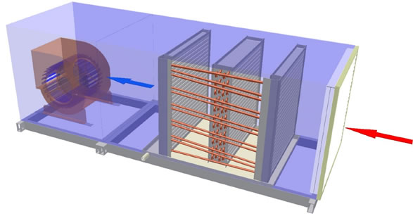
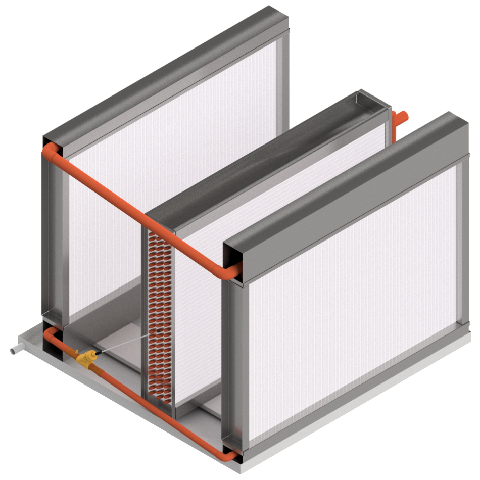
Wrap-Around Dehumidifier Heat Pipes installed in cooling coil section
DHP-U™: U-Frame Dehumidifier Heat Pipes
Features
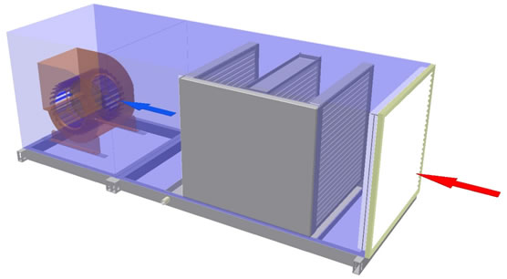
These units are completely fabricated at the HPT factory and can be installed around a cooling coil without assistance by HPT technicians. They can be slid into place horizontally or dropped into place from above.
Applications
Typically installed by custom air conditioning unit manufacturers around chilled water or DX cooling coils.
Controllable Dehumidifier Heat Pipe Systems
DHP-FC™: Factory Installed Controllable Dehumidifier Heat Pipes
DHP-SC™: Site Installed Controllable Dehumidifier Heat Pipes
DHP-UC™: U-Frame Controllable Dehumidifier Heat Pipes
DHP-V™: Vertical Tube Wrap-Around Dehumidifier Heat Pipes
Features
Wrap-around heat pipes are normally installed as passive devices designed to match the requirements of their installation. Sometimes the need for maximum sensible cooling overrides the need for humidity control. Because of this, it is necessary to temporarily lower or shut off the reheat action of the heat pipe.
However, when reheat is shut off, the precool also shuts off, increasing the load on the cooling coil. Unless the cooling coil has extra capacity, the cooling coil leaving air temperature and dewpoint will be higher than with the heat pipe operating. There will still be more sensible cooling available than with the heat pipe operating, just not as much as it would first appear. For example, many cooling coils have a 55° F saturated leaving air temperature. With a typical two row wrap-around heat pipe, the reheat is about 10° F, warming the air to 65° F. Shutting off the reheat and the precool means a cooling coil with a fixed capacity, or one already operating at maximum capacity, may only be able to cool the air to a dew point between 58° F and 62° F. The need for the heat pipe performance to be less than the maximum but more than zero brings about the need for controllable heat pipes.
Applications
Typically used for applications where there is limited cooling capacity or where dehumidification needs to be closely controlled, or variable reheat requirement.
Following are the two main applications for controlling Dehumidifier Heat Pipes:
1. Electrically Operated Solenoid Valves, DHP-FC™, DHP-SC™, DHP-UC™
For remote control of an operating heat pipe, normally open (NO) electric solenoid valves can be installed in the liquid return lines of the individual heat pipe circuits. The number of valves needed is determined by the size of the heat pipe, the number of rows, and the degree of control desired. It may not be necessary to install controls on all circuits if partial control is sufficient. The total heat pipe system can have a mix of controlled and uncontrolled circuits for systems that do not require shutting off 100% of the heat pipe operation.
As the heat pipe size and/or number of rows increase, the number of valves increases. When the installation calls for approximately 15 or more solenoids, the 30 Watts of electrical power needed to operate each also becomes an important consideration. In this case consideration should be given to 115 VAC solenoids to avoid the added cost of having to install large power transformers, or to consider a different control option.
Heat pipes with control solenoids can be installed in factory fitted wrap-around heat pipes and in U-framed heat pipes. The size of the solenoids adds considerable depth to the heat pipe connection section (F dimension). The cooling coil may need to be ordered shorter than normal, or the AHU section ordered wider than normal, in order to accommodate the solenoids. In some cases, where this is not possible, an outside enclosure is built to house the connecting section of the heat pipes. In addition, this area must have access after the AHU is installed. One row of solenoids (for a one or two rows heat pipes) needs a connection section depth of 5 inches; two rows of solenoids (for a three or four rows heat pipes) need a depth of 9 inches. These dimensions are illustrated right.
The circuiting required for installing solenoids lends itself to building the heat pipe with multiples of two rows only. A three row controllable requires the same number of solenoids as a four row controllable.
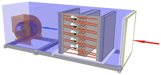
Solenoid Valve Controlled Heat Pipe System
Valve Control Examples
| Total No. of Stages | % Heat Pipe Effect |
| 3 | 0, 33, 66, 100 |
| 4 | 0, 25, 50, 75, 100 |
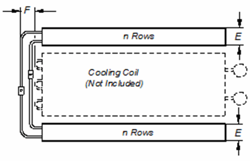
| Rows | E | F- W/O Valves |
F-W/ Valves |
| 1 | 2.25 | 1.50 | 5.00 |
| 2 | 3.25 | 2.00 | 5.00 |
| 3 | 4.25 | 2.75 | 9.00 |
| 4 | 5.50 | 3.25 | 9.00 |
| 5 | 6.75 | 4.00 | 13.00 |
| 6 | 8.00 | 4.50 | 13.00 |
2. Vertical Tube Wrap-Around Dehumidifier Heat Pipes, DHP-V™
The manifolded heat pipe allows controllability by using a different heat pipe construction method. The heat pipe coils are built with vertical tubes manifold together at the top and at the bottom, creating a vapor line at the top and a liquid line at the bottom. There are only two lines per circuit crossing over between the two heat pipe sections, although they are quite a bit larger than the normal ½ inch crossover tubes used in regular heat pipe systems. The vapor line is typically 1.625 or 2.125 inches OD while the liquid line is typically 1.375 inches OD. By installing a proportional control electronic refrigeration valve in the liquid line, the liquid return can be controlled thus controlling the heat pipe performance. These heat pipes can be installed in multiple banks high.
An electric step motor valve is typically used to provide modulating control. The valves are controlled from a separate HPT furnished control box including microprocessor(s), with signals originating from the Building Automation System, which provides the sensors and is programmed to operate the heat pipe system to control the supply leaving air temperature as required.
This design only uses electric power when the valve setting is changing. The top and bottom manifolds do reduce the available finned area, making this design most suitable for large installations. In units up to about 30 inches of finned height, solenoid valves should be considered; for larger units, manifolded heat pipes should be considered. There are also other considerations. This product is not available for selection in our online software SelectPlus™. Please contact HPT for advice.
Schematic of a Vertical Tube Controllable
DHP-V™, Heat Pipe and Cooling Coil